INDUSTRIAL MACHINERY SALES
Industrial Machinery Sales
Japanese machinery.
From cold forming to precision finishing.
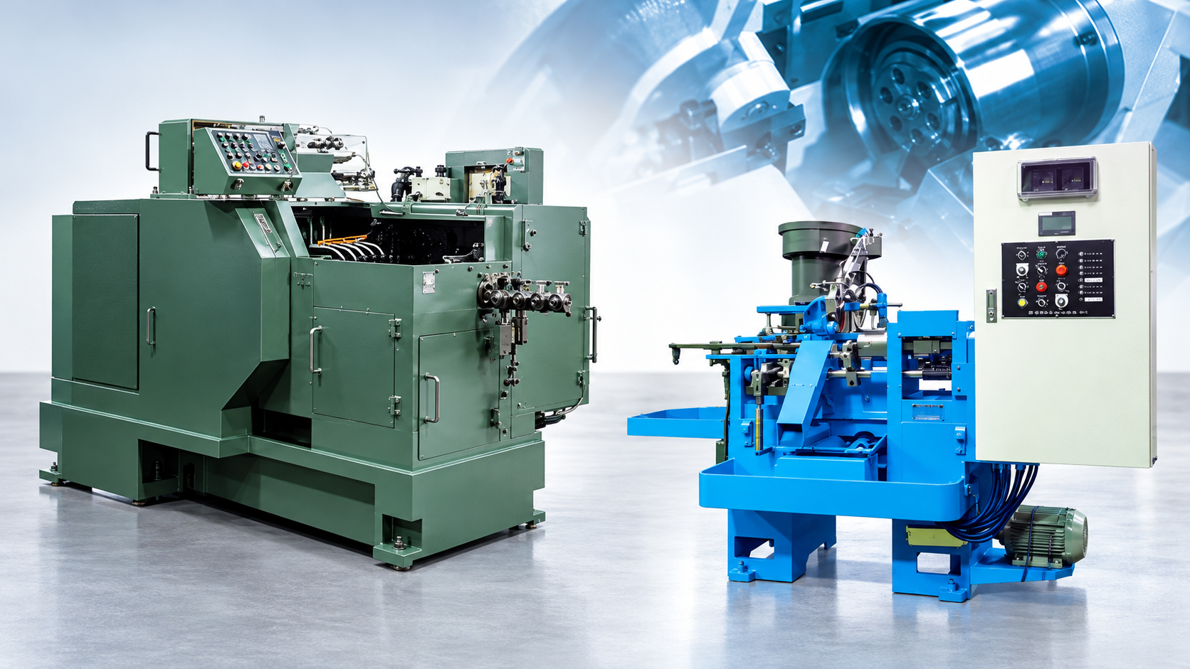
Specialist production equipment for manufacturers of small metal components, supported by practical technical and commercial coordination.
Nexus Bravo represents Matsumoto Machinery and Maeba Tekko for industrial machinery sales. We connect customer applications with manufacturer review, helping overseas buyers define equipment requirements, evaluate the proposed machine configuration and move toward a clearly scoped quotation.

MATSUMOTO MACHINERY
YMP MICRO SERIES · MICRO PARTS FORMER
YMP Micro series — machine and tooling overview.
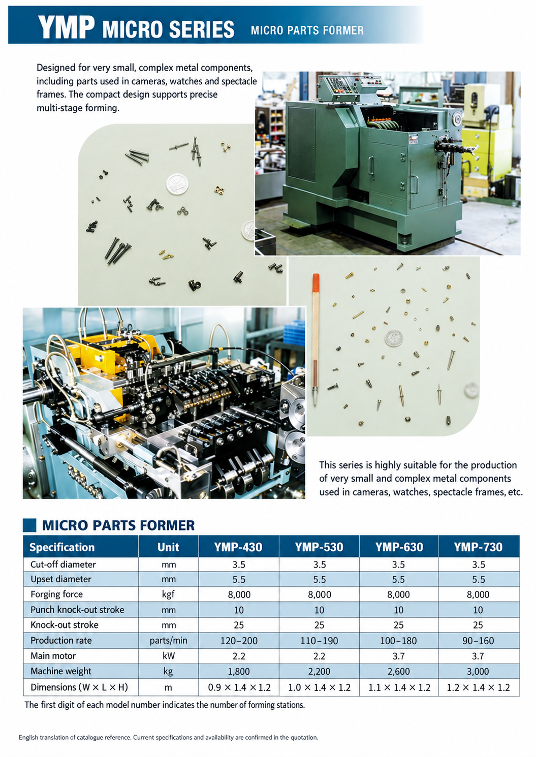
Compact equipment for intricate small components.
The YMP Micro series is designed for very small, complex metal components, including parts used in cameras, watches and spectacle frames. The catalogue presents a compact machine design, an internal view of the forming tools and examples of miniature formed components.
Discuss your component drawing, material and production target with Nexus Bravo. We coordinate model selection and tooling enquiries with Matsumoto Machinery.
Open English YMP Micro catalogue page ↗
English translation of the catalogue reference. Current specifications and model availability are confirmed with the manufacturer for your quotation.
View the catalogue specifications in English
This catalogue edition lists the following values. Its production rates and installation dimensions differ from the manufacturer’s published specifications shown elsewhere on this page; use the quotation for the proposed machine’s confirmed specification.
| Specification | YMP-430 | YMP-530 | YMP-630 | YMP-730 |
|---|---|---|---|---|
| Cut-off diameter (mm) | 3.5 | 3.5 | 3.5 | 3.5 |
| Upset diameter (mm) | 5.5 | 5.5 | 5.5 | 5.5 |
| Forging force (kgf) | 8,000 | 8,000 | 8,000 | 8,000 |
| Punch knock-out stroke (mm) | 10 | 10 | 10 | 10 |
| Knock-out stroke (mm) | 25 | 25 | 25 | 25 |
| Production rate (parts/min) | 120–200 | 110–190 | 100–180 | 90–160 |
| Main motor (kW) | 2.2 | 2.2 | 3.7 | 3.7 |
| Machine weight (kg) | 1,800 | 2,200 | 2,600 | 3,000 |
| Dimensions — W × L × H (m) | 0.9 × 1.4 × 1.2 | 1.0 × 1.4 × 1.2 | 1.1 × 1.4 × 1.2 | 1.2 × 1.4 × 1.2 |
The first digit in the model number indicates the number of forming stations. YMP-730 is included as a catalogue reference; current supply availability requires manufacturer confirmation.
Micro parts forming.
Multi-stage capability.
Matsumoto Machinery specialises in multi-stage cold forming equipment. Its YMP Micro series addresses small metal components through successive forming stages, with machine selection based on the part geometry, material and production requirement.
Cold forming establishes component geometry through controlled plastic deformation. A productive application depends on the forming sequence, tooling and material behaviour as well as the machine’s nominal capacity. We coordinate the drawing and technical questions needed for the manufacturer to assess the proposed process.
The YMP Micro models featured here are YMP-430, YMP-530 and YMP-630; current specifications and supply availability are confirmed with Matsumoto Machinery when preparing your quotation.
Inside the forming cycle
Five stations. One evolving component.
A longer blank enters the first die, develops through five forming strokes and leaves as a stepped component with a formed recess and external head profile. The 3D film combines synchronised multi-station operation with close-up views of the shape developed at each stage.
Read the five-station sequence
- Head preform: a longer cut blank is upset to establish a wider head.
- Extruded shank: forward extrusion reduces the shank diameter and extends its length.
- Flange and shoulder: the next die develops the stepped body and flange.
- Blind recess: backward extrusion introduces a formed cavity.
- Hexagonal head: the final station forms the external head profile and sizes the body. The completed part is ejected, transferred clear of the tools and released into the discharge tray.
The film shows different workpieces at successive stages, including synchronised operation and close-up views. Actual stage designs, transfer systems and operation sequences depend on the component and machine.
Coordinated slide, knock-out and transfer.
The die stations sit side by side, with horizontal working axes and punches mounted on the opposing slide. In continuous production, the slide works on different blanks at their respective stages during the same stroke. The animation shows different workpieces at successive stages, with close-up views of forming and transfer.
After forming, the punches retract. Knock-out mechanisms bring the blanks clear of the dies, and transfer fingers carry them to the next station. Tool withdrawal, ejection, grip and transfer must be coordinated before the following stroke. The final workpiece is released to discharge.
Station count follows the process.
Additional stations can divide a demanding operation or create intermediate shapes. They are not, by themselves, a measure of component quality. Geometry, alloy, stage reductions, tooling and the ability to locate and transfer the blank determine the appropriate machine arrangement.
YMP Micro series overview
- YMP-430, YMP-530 and YMP-630 configurations listed by the manufacturer.
- Four, five or six forming stations respectively.
- Applications reviewed against the drawing, wire material, required dimensions and output target.
YMP Micro model comparison
| Published specification | YMP-430 | YMP-530 | YMP-630 |
|---|---|---|---|
| Forming stations | 4 | 5 | 6 |
| Production rate (parts/min) | 80–210 | 70–200 | 60–190 |
| Motor power (kW) | 2.2 | 2.2 | 2.2 |
| Machine weight (kg) | 1800 | 2000 | 2200 |
| Width × length × height (m) | 1.75 × 0.90 × 1.39 | 1.75 × 0.94 × 1.39 | 1.75 × 0.98 × 1.39 |
Source: Matsumoto Machinery’s published YMP Micro specifications, checked 20 October 2026. The production rate achievable for your component, equipment scope and installation requirements are confirmed in the quotation.
Common specifications — YMP Micro series
| Specification | Value |
|---|---|
| Cut-off diameter | 3.5 mm |
| Upset diameter | 5.5 mm |
| Forging force | 8,000 kgf |
| Punch knock-out (PKO) stroke | 10 mm |
| Knock-out (KO) stroke | 25 mm |
Reference: Matsumoto Machinery — official product information. Your quotation will specify the production rate, motor power, machine weight and installation dimensions for the proposed model and configuration.
YMP PARTS FORMER SERIES
Formed shanks, heads and holes.
A process built around the component.
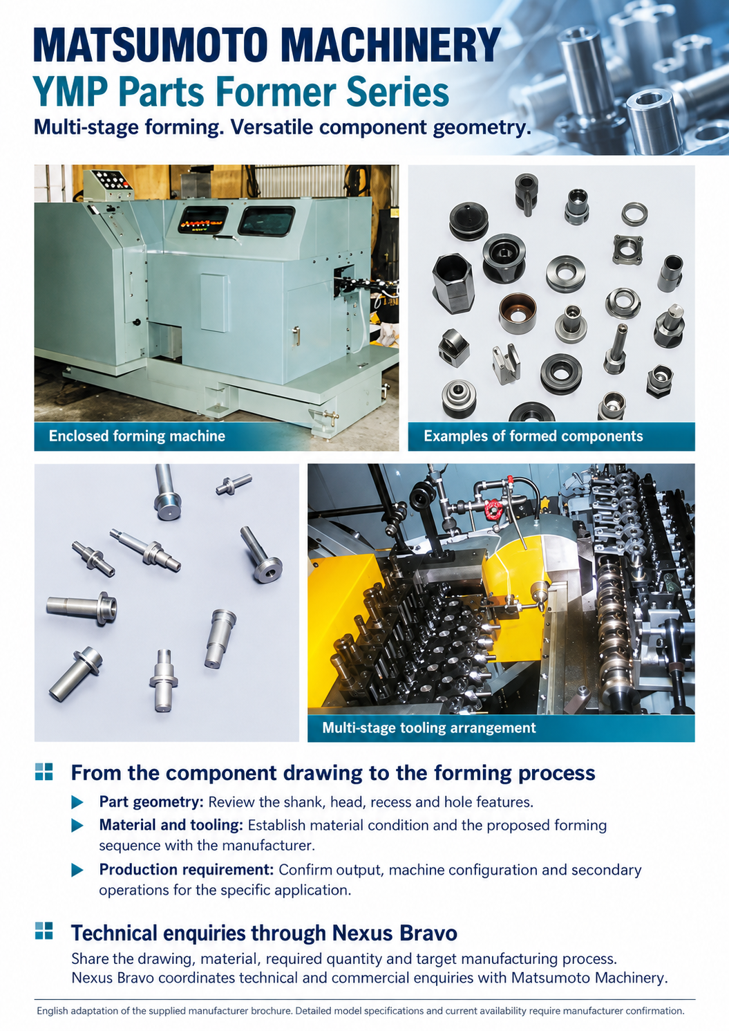
The YMP product brochure presents multi-stage forming equipment for components with shanks and holes, together with examples of formed parts and the tooling arrangement. The proposed machine and process are reviewed against the component drawing.
- Clarify the required shank, head, recess and hole geometry.
- Review material condition, forming sequence and tooling with the manufacturer.
- Confirm production quantity, machine configuration and any secondary operations.
Share the part drawing, material and production objective with Nexus Bravo to begin a machinery enquiry.
Define the requirement beyond headline output.
- Material and blank: alloy grade, incoming condition, wire diameter and cut length.
- Forming envelope: head, shank and recess geometry, required reductions and forming load.
- Handling: grip surfaces, knock-out travel, transfer clearance and discharge method.
- Production: target output for the proposed part, changeover frequency and intended operating pattern.
- Tooling and installation: punch and die scope, trial requirements, replacement arrangements, available space, utilities and guarding.
For small or thin-walled components, locating and releasing the blank can be as important as nominal machine capacity. The manufacturer reviews the component drawing and material before proposing a model and tooling arrangement.

MAEBA TEKKO · CAM-OPERATED SECONDARY PROCESSING
Dedicated machining.
Precision beyond the primary process.
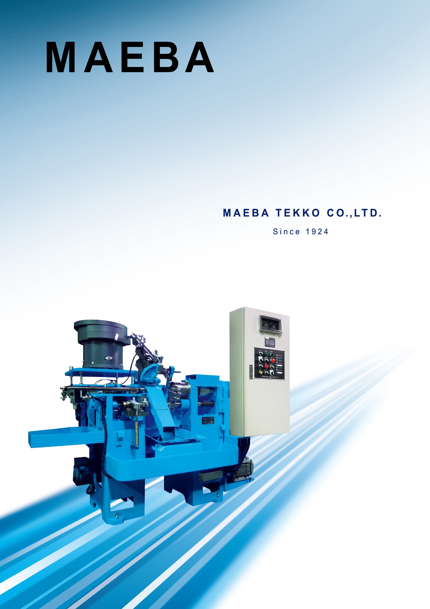
Maeba Tekko’s cam-operated automatic machines perform secondary cutting operations on previously formed or machined components. Their mechanical operating sequence provides a dedicated approach to repetitive production, with the equipment arranged around the workpiece and required machining steps.
Secondary cutting is used selectively. Where cold forming can achieve the specified geometry, tolerance and finish, additional machining may be unnecessary. Maeba Tekko’s equipment is considered for features that cannot suitably be formed, or for surfaces and dimensions that require a separate cutting operation.
The SP-3 supports tapering, grooving, slotting, drilling and other operations performed with a rotating workpiece. Appropriate component changes allow different primary-processed workpiece shapes to be accommodated.
Timers, chip conveyors and sensors may be incorporated to support defined periods of unattended operation and operation with reduced staffing. Suitability depends on the application, feeding arrangement, tooling and selected configuration.
MAEBA TEKKO · MACHINE OPERATION
Precision secondary machining in operation.
Watch two machine-operation videos showing the workholding, cutting area and mechanical movements from different viewpoints. Secondary machining is selected where the component drawing requires features, dimensions or finishes that cannot suitably be achieved by cold forming alone.
Close-up and wider views of the machining area and operating mechanism. Duration: 1 min 13 sec.
A longer view of the equipment in operation, including the machining area and mechanical movements. Duration: 2 min 47 sec.
Why consider cam-operated secondary processing?
Visible mechanical operation
The operating motion can be observed directly, supporting setup, adjustment and the development of practical operator knowledge.
Application-focused cutting
A dedicated machine arrangement can be evaluated against the required feature, production cycle and quantity. Speed and accuracy are established for the actual workpiece.
Serviceable construction
The manufacturer’s brochure emphasises mechanical construction and replacement-parts support. Parts availability, response times and service location are confirmed individually.
Start with the blank and the datum.
The incoming blank and finished component drawings should be reviewed together. Identify the locating face or diameter, clamping length, unsupported overhang, finishing allowance and any orientation requirement. The proposed setup must hold the component consistently without unacceptable distortion.
Loading, checking and discharge are part of the application review. An operation that is straightforward on a hand-loaded sample may need further feeding and workholding development for repetitive automatic production.
Cam-operated production has a dedicated mechanical sequence.
Cam motion defines the machining cycle around a repeatable workpiece and specified operations. This can suit an established component family with recurring demand. Product variety, changeovers and setup requirements should also be assessed when comparing dedicated mechanical equipment with a programmable machining route.
Review cutting stability and chip control.
Workholding and tool support influence dimensional control and surface finish. Excessive overhang can reduce stability, so the cutting tool, clamping arrangement and supported length should be considered together.
For hole making, chips must leave the cutting zone reliably. Cutting data, coolant, chip handling and tool-change arrangements are selected for the material and hole geometry. Equipment capacity alone does not establish finished-part accuracy or production rate.
SP-3 principal specifications
| Spindle size | Ø50 mm | Ø60 mm | Ø70 mm |
|---|---|---|---|
| Workpiece diameter | Ø2–Ø10 mm | Up to Ø15 mm | Up to Ø20 mm |
| Approximate overhanging head diameter | Ø20 mm | Ø26 mm | Ø36 mm |
| Workpiece length | Up to 70 mm; optional configuration up to 100 mm | Up to 70 mm; optional configuration up to 100 mm | Up to 70 mm; optional configuration up to 100 mm |
Capacities depend on workpiece conditions. Optional and special configurations require manufacturer review.
Special configurations
| Model | Application / configuration |
|---|---|
| SL-4 | Long workpieces up to approximately 300 mm; mainly straight parts supported by guides during cutting. |
| MH-3 | Higher-speed processing of simpler cutting operations. |
| SS-3 | Straight workpieces without flanges, up to approximately 150 mm. |
| SH-3 | Configuration equipped with a dedicated drilling unit. |
SDM-4 screwdriver profile processing
The SDM-4 is intended for the production of screwdriver tip profiles. The product brochure describes four-way and six-way profiles, together with special three-way or five-way arrangements. Tooling and profile requirements are reviewed for the proposed application.
Machine dimensions and approximate weight
| Model | Width × depth × height (mm) | Approximate weight (kg) |
|---|---|---|
| SP-3 | 1900 × 1250 × 1500 | 900 |
| SL-4 | 2100 × 1250 × 1500 | 1000 |
| MH-3 | 1900 × 1250 × 1500 | 900 |
| SDM-4 | 1700 × 900 × 1200 | 1200 |
| SS-3 | On request | On request |
| SH-3 | On request | On request |
Dimensions and weights vary with specification. These brochure reference values are not a foundation or installation drawing.
Applications, customisation and service
Maeba Tekko’s brochure describes experience with automotive component machining in Japan and overseas, appliance and construction-related products, and additional machining of existing components. Each new enquiry begins with a review of the part and the required operations.
Requests can cover changeover, special-component setup, custom parts, special specifications and repair consultation. Nexus Bravo coordinates the enquiry with the manufacturer; the service provider, location, travel arrangements, parts supply and responsibilities are established for the specific engagement.
English brochure reference
Review the manufacturer’s operating approach, machining examples, product range and reference specifications in English.
Manufacturer reference: Maeba Tekko — official product information.
Application and acceptance
Define what a successful machine trial will demonstrate.
Begin with a controlled component drawing and representative material. Agree the features to be measured, the inspection method and the operating conditions for the trial. Define whether quoted output refers to strokes, discharged parts or accepted finished components.
Before order placement, clarify tooling and spare-parts scope, changeovers, documentation, training, site preparation, commissioning and support responsibilities. Where forming and selective machining are combined, review the blank, feeding, machining datum, cleaning and inspection as one coherent route.
OUR ROLE
One coordinated route from enquiry to proposal.
Application review
Organise the drawing, material, process objective and production target for manufacturer evaluation.
Technical coordination
Coordinate questions on tooling, workpiece handling, machine configuration and evaluation requirements.
Commercial definition
Clarify quotation scope, delivery basis and the responsibilities for installation, training and after-sales support before order placement.
Start with the component.
Define the production requirement.
Send your drawing or specification with the material, target quantity, required operation and installation country. If a process is already in use, include the current manufacturing route and the improvement you want to evaluate.
Discuss a machinery requirement
Drawings and specifications may be attached through our contact form. Equipment availability, performance, tooling and service arrangements are subject to manufacturer confirmation and the agreed quotation.