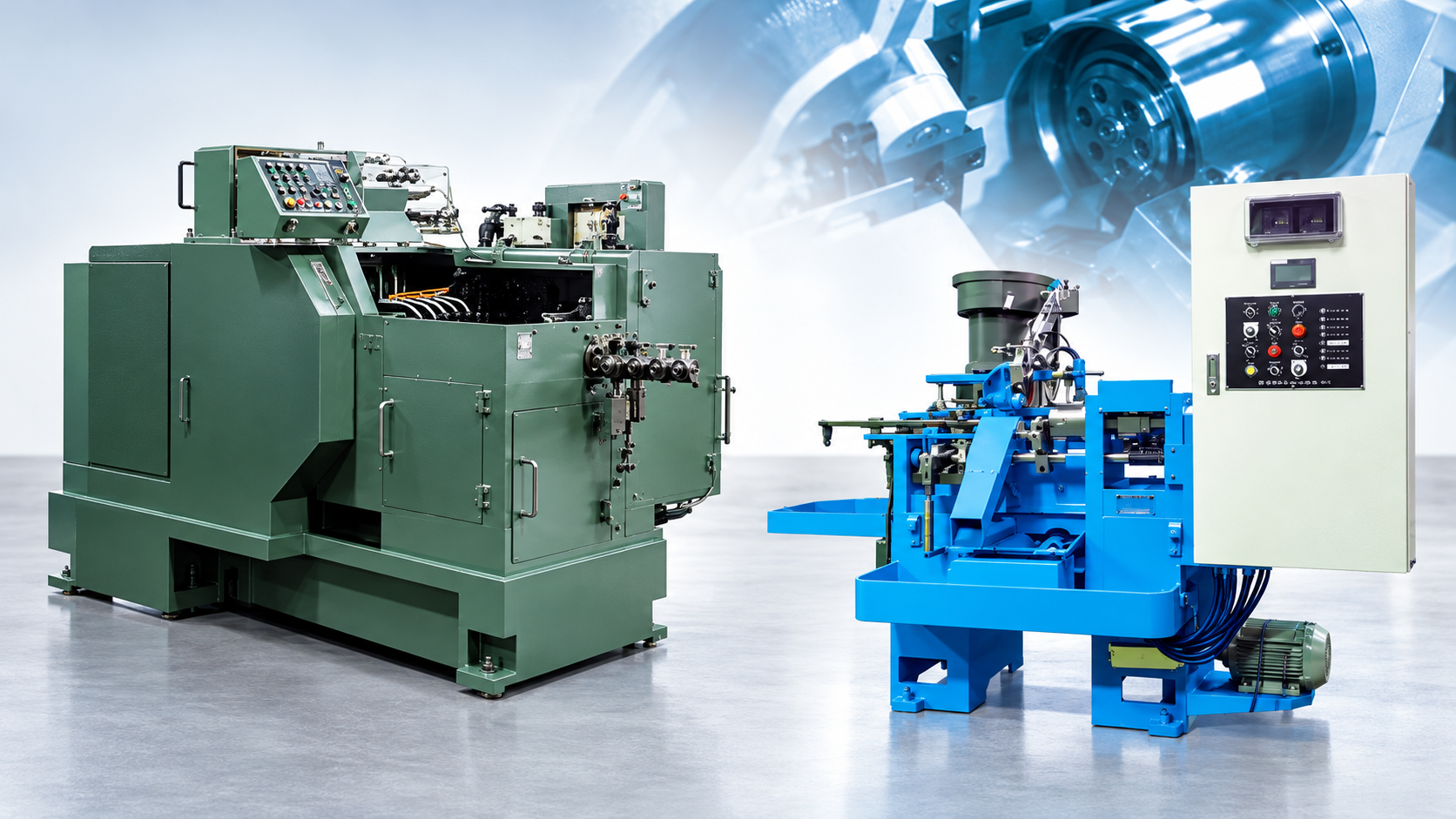
औद्योगिक मशीनरी की बिक्री
औद्योगिक मशीनरी बिक्री
जापानी मशीनरी।
कोल्ड फॉर्मिंग से परिशुद्ध फिनिशिंग तक।
छोटे धातु घटकों के निर्माताओं के लिए विशिष्ट उत्पादन उपकरण, व्यावहारिक तकनीकी और वाणिज्यिक समन्वय के सहयोग से।
Nexus Bravo औद्योगिक मशीनरी बिक्री के लिए Matsumoto Machinery और Maeba Tekko का प्रतिनिधित्व करता है। हम ग्राहक अनुप्रयोगों को निर्माता समीक्षा से जोड़कर विदेशी खरीदारों को उपकरण आवश्यकताएँ निर्धारित करने, प्रस्तावित विन्यास का मूल्यांकन करने और स्पष्ट कार्यक्षेत्र वाले मूल्य-प्रस्ताव की ओर बढ़ने में सहयोग करते हैं।

MATSUMOTO MACHINERY
YMP MICRO SERIES · MICRO PARTS FORMER
YMP Micro series — machine and tooling overview.
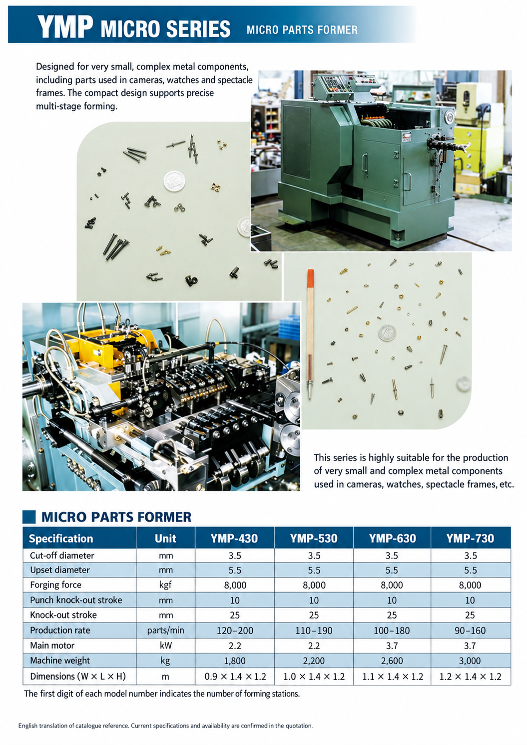
Compact equipment for intricate small components.
The YMP Micro series is designed for very small, complex metal components, including parts used in cameras, watches and spectacle frames. The catalogue presents a compact machine design, an internal view of the forming tools and examples of miniature formed components.
Discuss your component drawing, material and production target with Nexus Bravo. We coordinate model selection and tooling enquiries with Matsumoto Machinery.
Open English YMP Micro catalogue page ↗
English translation of the catalogue reference. Current specifications and model availability are confirmed with the manufacturer for your quotation.
View the catalogue specifications in English
This catalogue edition lists the following values. Its production rates and installation dimensions differ from the manufacturer’s published specifications shown elsewhere on this page; use the quotation for the proposed machine’s confirmed specification.
| Specification | YMP-430 | YMP-530 | YMP-630 | YMP-730 |
|---|---|---|---|---|
| Cut-off diameter (mm) | 3.5 | 3.5 | 3.5 | 3.5 |
| Upset diameter (mm) | 5.5 | 5.5 | 5.5 | 5.5 |
| Forging force (kgf) | 8,000 | 8,000 | 8,000 | 8,000 |
| Punch knock-out stroke (mm) | 10 | 10 | 10 | 10 |
| Knock-out stroke (mm) | 25 | 25 | 25 | 25 |
| Production rate (parts/min) | 120–200 | 110–190 | 100–180 | 90–160 |
| Main motor (kW) | 2.2 | 2.2 | 3.7 | 3.7 |
| Machine weight (kg) | 1,800 | 2,200 | 2,600 | 3,000 |
| Dimensions — W × L × H (m) | 0.9 × 1.4 × 1.2 | 1.0 × 1.4 × 1.2 | 1.1 × 1.4 × 1.2 | 1.2 × 1.4 × 1.2 |
The first digit in the model number indicates the number of forming stations. YMP-730 is included as a catalogue reference; current supply availability requires manufacturer confirmation.
माइक्रो पुर्जों की फॉर्मिंग।
बहु-चरणीय क्षमता।
Matsumoto Machinery specialises in multi-stage cold forming equipment. Its YMP Micro series addresses small metal components through successive forming stages, with machine selection based on the part geometry, material and production requirement.
Cold forming establishes component geometry through controlled plastic deformation. A productive application depends on the forming sequence, tooling and material behaviour as well as the machine’s nominal capacity. We coordinate the drawing and technical questions needed for the manufacturer to assess the proposed process.
यहाँ प्रस्तुत YMP Micro मॉडल YMP-430, YMP-530 और YMP-630 हैं। मूल्य-प्रस्ताव तैयार करते समय वर्तमान विनिर्देशों और आपूर्ति की उपलब्धता की पुष्टि Matsumoto Machinery से की जाती है।
Inside the forming cycle
Five stations. One evolving component.
A longer blank enters the first die, develops through five forming strokes and leaves as a stepped component with a formed recess and external head profile. The 3D film combines synchronised multi-station operation with close-up views of the shape developed at each stage.
Read the five-station sequence
- Head preform: a longer cut blank is upset to establish a wider head.
- Extruded shank: forward extrusion reduces the shank diameter and extends its length.
- Flange and shoulder: the next die develops the stepped body and flange.
- Blind recess: backward extrusion introduces a formed cavity.
- Hexagonal head: the final station forms the external head profile and sizes the body. The completed part is ejected, transferred clear of the tools and released into the discharge tray.
The film shows different workpieces at successive stages, including synchronised operation and close-up views. Actual stage designs, transfer systems and operation sequences depend on the component and machine.
Coordinated slide, knock-out and transfer.
The die stations sit side by side, with horizontal working axes and punches mounted on the opposing slide. In continuous production, the slide works on different blanks at their respective stages during the same stroke. The animation shows different workpieces at successive stages, with close-up views of forming and transfer.
After forming, the punches retract. Knock-out mechanisms bring the blanks clear of the dies, and transfer fingers carry them to the next station. Tool withdrawal, ejection, grip and transfer must be coordinated before the following stroke. The final workpiece is released to discharge.
Station count follows the process.
Additional stations can divide a demanding operation or create intermediate shapes. They are not, by themselves, a measure of component quality. Geometry, alloy, stage reductions, tooling and the ability to locate and transfer the blank determine the appropriate machine arrangement.
YMP Micro शृंखला का परिचय
- निर्माता द्वारा सूचीबद्ध YMP-430, YMP-530 और YMP-630 विन्यास।
- क्रमशः चार, पाँच या छह फॉर्मिंग स्टेशन।
- अनुप्रयोगों की समीक्षा ड्रॉइंग, तार की सामग्री, आवश्यक आयाम और उत्पादन लक्ष्य के आधार पर होती है।
YMP Micro model comparison
| Published specification | YMP-430 | YMP-530 | YMP-630 |
|---|---|---|---|
| Forming stations | 4 | 5 | 6 |
| Production rate (parts/min) | 80–210 | 70–200 | 60–190 |
| Motor power (kW) | 2.2 | 2.2 | 2.2 |
| Machine weight (kg) | 1800 | 2000 | 2200 |
| Width × length × height (m) | 1.75 × 0.90 × 1.39 | 1.75 × 0.94 × 1.39 | 1.75 × 0.98 × 1.39 |
Source: Matsumoto Machinery’s published YMP Micro specifications, checked 20 October 2026. The production rate achievable for your component, equipment scope and installation requirements are confirmed in the quotation.
Common specifications — YMP Micro series
| Specification | Value |
|---|---|
| कट-ऑफ व्यास | 3.5 mm |
| अपसेट व्यास | 5.5 mm |
| फॉर्मिंग बल | 8,000 kgf |
| पंच नॉक-आउट (PKO) स्ट्रोक | 10 mm |
| नॉक-आउट (KO) स्ट्रोक | 25 mm |
संदर्भ: Matsumoto Machinery — आधिकारिक उत्पाद जानकारी. आपके मूल्य-प्रस्ताव में प्रस्तावित मॉडल और विन्यास की उत्पादन दर, मोटर शक्ति, मशीन का वजन और स्थापना के आयाम दिए जाएँगे।
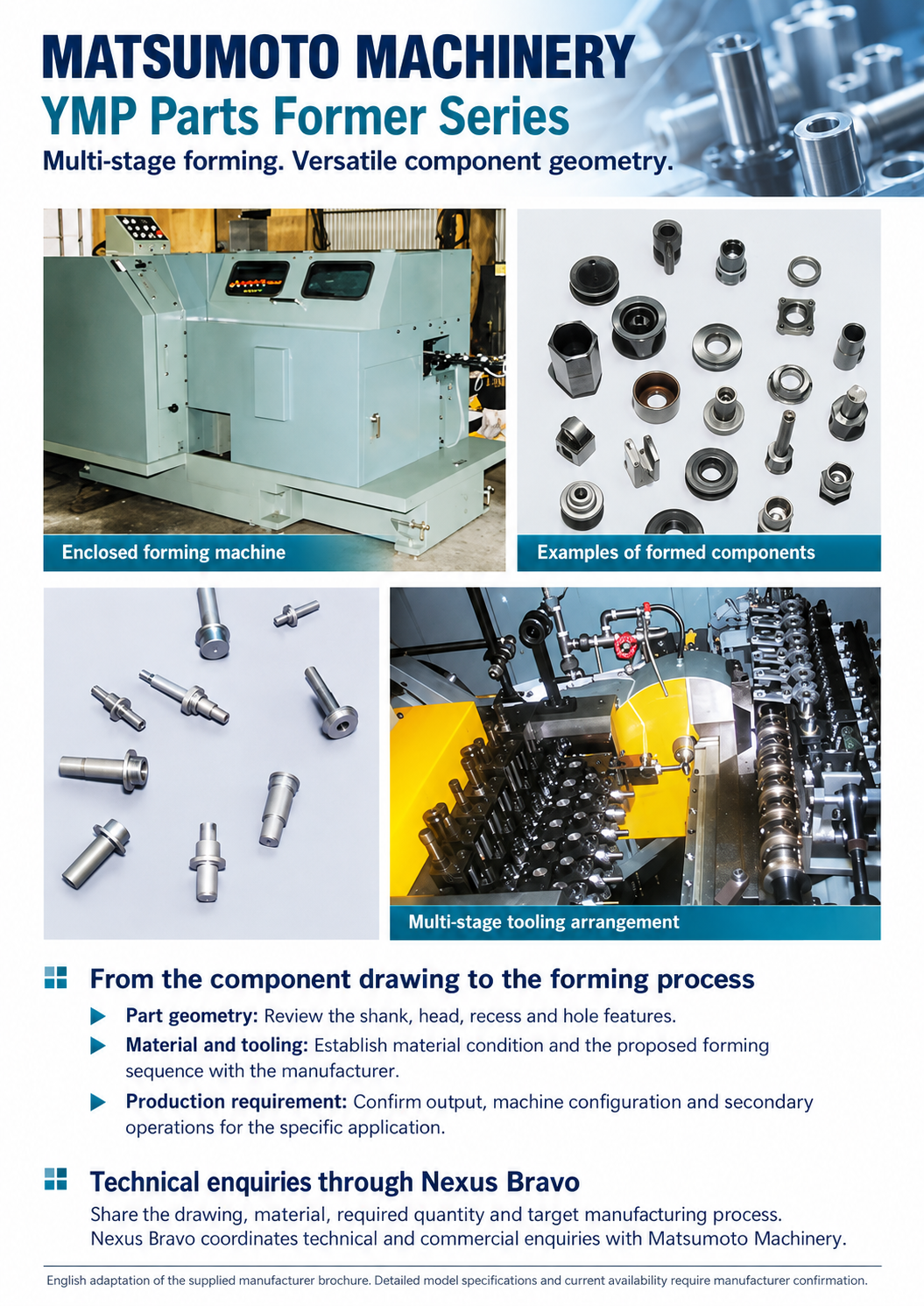
YMP पार्ट्स फॉर्मर शृंखला
फॉर्मिंग द्वारा बने शैंक, हेड और छिद्र।
घटक के अनुसार विकसित प्रक्रिया।
The YMP product brochure presents multi-stage forming equipment for components with shanks and holes, together with examples of formed parts and the tooling arrangement. The proposed machine and process are reviewed against the component drawing.
- आवश्यक शैंक, हेड, रिसेस और छिद्र की ज्यामिति स्पष्ट करें।
- निर्माता के साथ सामग्री अवस्था, फॉर्मिंग क्रम और टूलिंग की समीक्षा करें।
- उत्पादन मात्रा, मशीन विन्यास और आवश्यक द्वितीयक प्रक्रियाओं की पुष्टि करें।
मशीनरी पूछताछ शुरू करने के लिए Nexus Bravo को पुर्जे की ड्रॉइंग, सामग्री और उत्पादन उद्देश्य भेजें।
Define the requirement beyond headline output.
- Material and blank: alloy grade, incoming condition, wire diameter and cut length.
- Forming envelope: head, shank and recess geometry, required reductions and forming load.
- Handling: grip surfaces, knock-out travel, transfer clearance and discharge method.
- Production: target output for the proposed part, changeover frequency and intended operating pattern.
- Tooling and installation: punch and die scope, trial requirements, replacement arrangements, available space, utilities and guarding.
For small or thin-walled components, locating and releasing the blank can be as important as nominal machine capacity. The manufacturer reviews the component drawing and material before proposing a model and tooling arrangement.

MAEBA TEKKO · कैम-संचालित द्वितीयक प्रसंस्करण
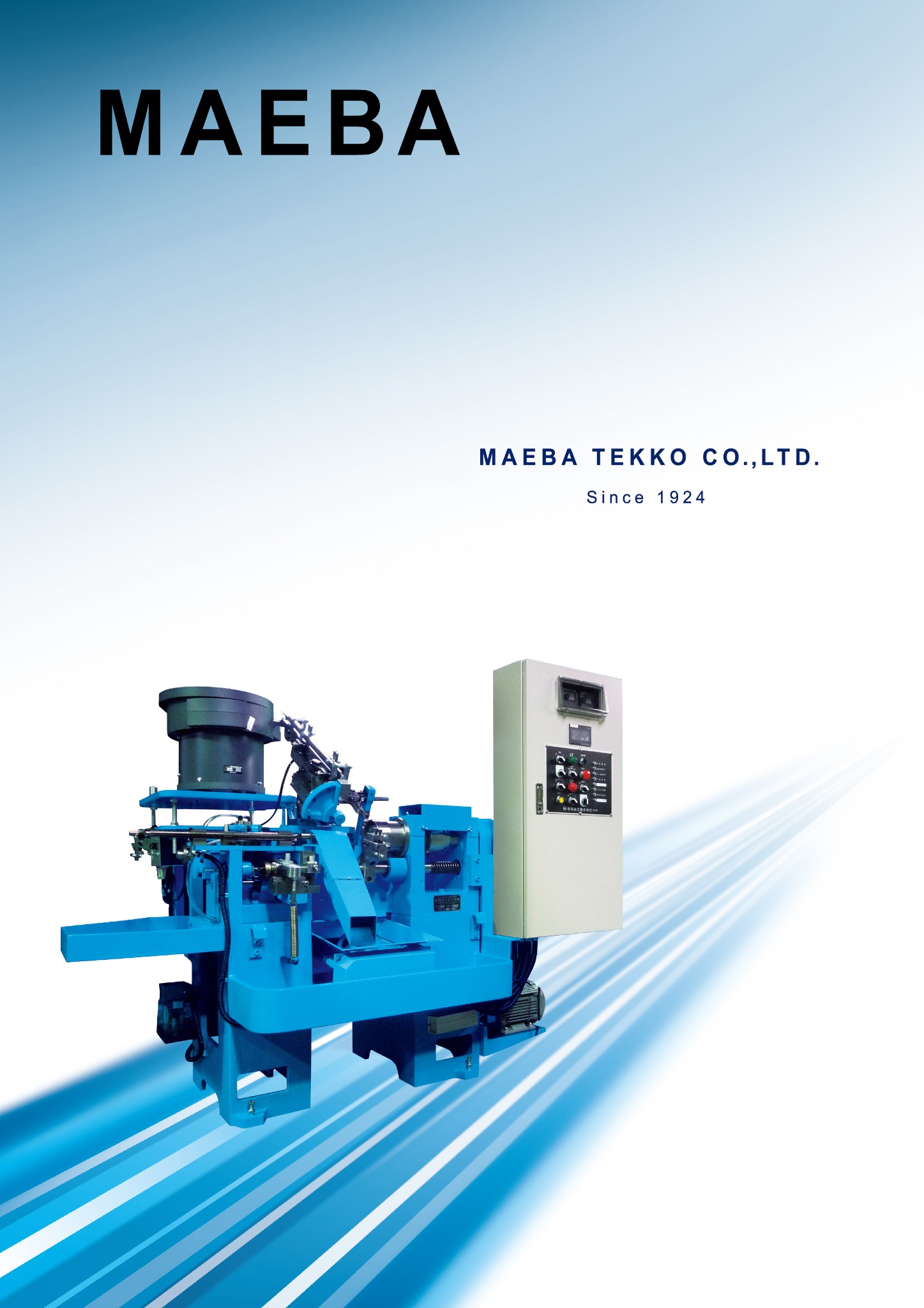
विशिष्ट मशीनिंग।
प्राथमिक प्रक्रिया से आगे की परिशुद्धता।
Maeba Tekko की कैम-संचालित स्वचालित मशीनें पहले से फॉर्म्ड या मशीन किए गए घटकों पर द्वितीयक कटिंग करती हैं। उनका यांत्रिक परिचालन क्रम दोहराव वाले उत्पादन के लिए समर्पित व्यवस्था देता है, जिसे वर्कपीस और आवश्यक मशीनिंग चरणों के अनुसार विन्यस्त किया जाता है।
Secondary cutting is used selectively. Where cold forming can achieve the specified geometry, tolerance and finish, additional machining may be unnecessary. Maeba Tekko’s equipment is considered for features that cannot suitably be formed, or for surfaces and dimensions that require a separate cutting operation.
The SP-3 supports tapering, grooving, slotting, drilling and other operations performed with a rotating workpiece. Appropriate component changes allow different primary-processed workpiece shapes to be accommodated.
टाइमर, चिप कन्वेयर और सेंसर जोड़कर निर्धारित समय तक बिना ऑपरेटर तथा कम कर्मियों के साथ संचालन में सहायता मिल सकती है। उपयुक्तता अनुप्रयोग, फीडिंग व्यवस्था, टूलिंग और चुने हुए विन्यास पर निर्भर है।
MAEBA TEKKO · MACHINE OPERATION
Precision secondary machining in operation.
Watch two machine-operation videos showing the workholding, cutting area and mechanical movements from different viewpoints. Secondary machining is selected where the component drawing requires features, dimensions or finishes that cannot suitably be achieved by cold forming alone.
Close-up and wider views of the machining area and operating mechanism. Duration: 1 min 13 sec.
A longer view of the equipment in operation, including the machining area and mechanical movements. Duration: 2 min 47 sec.
कैम-संचालित द्वितीयक प्रसंस्करण पर विचार क्यों करें?
प्रत्यक्ष दिखाई देने वाला यांत्रिक संचालन
मशीन की गति सीधे देखी जा सकती है, जो सेटअप, समायोजन और व्यावहारिक ऑपरेटर कौशल के विकास में सहायक है।
अनुप्रयोग-केंद्रित कटिंग
समर्पित मशीन व्यवस्था का मूल्यांकन आवश्यक विशेषता, उत्पादन चक्र और मात्रा के अनुसार किया जा सकता है। गति और सटीकता वास्तविक वर्कपीस के लिए निर्धारित होती हैं।
रखरखाव-अनुकूल संरचना
The manufacturer’s brochure emphasises mechanical construction and replacement-parts support. Parts availability, response times and service location are confirmed individually.
Start with the blank and the datum.
The incoming blank and finished component drawings should be reviewed together. Identify the locating face or diameter, clamping length, unsupported overhang, finishing allowance and any orientation requirement. The proposed setup must hold the component consistently without unacceptable distortion.
Loading, checking and discharge are part of the application review. An operation that is straightforward on a hand-loaded sample may need further feeding and workholding development for repetitive automatic production.
Cam-operated production has a dedicated mechanical sequence.
Cam motion defines the machining cycle around a repeatable workpiece and specified operations. This can suit an established component family with recurring demand. Product variety, changeovers and setup requirements should also be assessed when comparing dedicated mechanical equipment with a programmable machining route.
Review cutting stability and chip control.
Workholding and tool support influence dimensional control and surface finish. Excessive overhang can reduce stability, so the cutting tool, clamping arrangement and supported length should be considered together.
For hole making, chips must leave the cutting zone reliably. Cutting data, coolant, chip handling and tool-change arrangements are selected for the material and hole geometry. Equipment capacity alone does not establish finished-part accuracy or production rate.
SP-3 के मुख्य विनिर्देश
| स्पिंडल आकार | Ø50 mm | Ø60 mm | Ø70 mm |
|---|---|---|---|
| वर्कपीस व्यास | Ø2–Ø10 mm | अधिकतम Ø15 mm | अधिकतम Ø20 mm |
| बाहर निकले हेड का अनुमानित व्यास | Ø20 mm | Ø26 mm | Ø36 mm |
| वर्कपीस लंबाई | Up to 70 mm; optional configuration up to 100 mm | Up to 70 mm; optional configuration up to 100 mm | Up to 70 mm; optional configuration up to 100 mm |
क्षमता वर्कपीस की स्थितियों पर निर्भर है। वैकल्पिक और विशेष विन्यासों के लिए निर्माता समीक्षा आवश्यक है।
विशेष विन्यास
| मॉडल | अनुप्रयोग / विन्यास |
|---|---|
| SL-4 | लगभग 300 mm तक लंबे वर्कपीस; मुख्यतः सीधे पुर्जे, जिन्हें कटिंग के दौरान गाइड का सहारा मिलता है। |
| MH-3 | सरल कटिंग प्रक्रियाओं का अधिक गति से प्रसंस्करण। |
| SS-3 | बिना फ्लैंज वाले सीधे वर्कपीस, लगभग 150 mm तक। |
| SH-3 | समर्पित ड्रिलिंग यूनिट वाला विन्यास। |
SDM-4 पेचकस टिप प्रोफाइल प्रसंस्करण
The SDM-4 is intended for the production of screwdriver tip profiles. The product brochure describes four-way and six-way profiles, together with special three-way or five-way arrangements. Tooling and profile requirements are reviewed for the proposed application.
मशीन के आयाम और अनुमानित वजन
| मॉडल | चौड़ाई × गहराई × ऊँचाई (mm) | अनुमानित वजन (kg) |
|---|---|---|
| SP-3 | 1900 × 1250 × 1500 | 900 |
| SL-4 | 2100 × 1250 × 1500 | 1000 |
| MH-3 | 1900 × 1250 × 1500 | 900 |
| SDM-4 | 1700 × 900 × 1200 | 1200 |
| SS-3 | अनुरोध पर | अनुरोध पर |
| SH-3 | अनुरोध पर | अनुरोध पर |
विनिर्देश के अनुसार आयाम और वजन बदलते हैं। ब्रोशर के ये संदर्भ आँकड़े नींव या स्थापना ड्रॉइंग नहीं हैं।
Applications, customisation and service
Maeba Tekko’s brochure describes experience with automotive component machining in Japan and overseas, appliance and construction-related products, and additional machining of existing components. Each new enquiry begins with a review of the part and the required operations.
अनुरोधों में चेंजओवर, विशेष घटक सेटअप, कस्टम पुर्जे, विशेष विनिर्देश और मरम्मत परामर्श शामिल हो सकते हैं। Nexus Bravo निर्माता के साथ पूछताछ का समन्वय करता है; सेवा प्रदाता, स्थान, यात्रा, पुर्जों की आपूर्ति और जिम्मेदारियाँ प्रत्येक कार्य के लिए तय होती हैं।
अंग्रेज़ी ब्रोशर संदर्भ
निर्माता की कार्यप्रणाली, मशीनिंग उदाहरण, उत्पाद श्रेणी और संदर्भ विनिर्देश अंग्रेज़ी में देखें।
निर्माता संदर्भ: Maeba Tekko — आधिकारिक उत्पाद जानकारी.
Application and acceptance
Define what a successful machine trial will demonstrate.
Begin with a controlled component drawing and representative material. Agree the features to be measured, the inspection method and the operating conditions for the trial. Define whether quoted output refers to strokes, discharged parts or accepted finished components.
Before order placement, clarify tooling and spare-parts scope, changeovers, documentation, training, site preparation, commissioning and support responsibilities. Where forming and selective machining are combined, review the blank, feeding, machining datum, cleaning and inspection as one coherent route.
हमारी भूमिका
पूछताछ से प्रस्ताव तक एक समन्वित प्रक्रिया।
अनुप्रयोग समीक्षा
Organise the drawing, material, process objective and production target for manufacturer evaluation.
तकनीकी समन्वय
टूलिंग, वर्कपीस हैंडलिंग, मशीन विन्यास और मूल्यांकन आवश्यकताओं संबंधी प्रश्नों का समन्वय।
वाणिज्यिक दायरा
ऑर्डर से पहले मूल्य-प्रस्ताव के दायरे, आपूर्ति आधार तथा स्थापना, प्रशिक्षण और बिक्री-पश्चात सहयोग की जिम्मेदारियाँ स्पष्ट करना।
घटक से शुरुआत करें।
उत्पादन आवश्यकता निर्धारित करें।
सामग्री, लक्षित मात्रा, आवश्यक प्रक्रिया और स्थापना देश सहित ड्रॉइंग या विनिर्देश भेजें। यदि कोई प्रक्रिया पहले से चल रही है, तो वर्तमान निर्माण प्रक्रिया और जिस सुधार का मूल्यांकन चाहते हैं वह भी बताएँ।
मशीनरी की आवश्यकता पर चर्चा करें
हमारे संपर्क फ़ॉर्म के माध्यम से ड्रॉइंग और विनिर्देश संलग्न कर सकते हैं। उपकरण उपलब्धता, प्रदर्शन, टूलिंग और सेवा व्यवस्थाएँ निर्माता की पुष्टि तथा सहमत मूल्य-प्रस्ताव के अधीन हैं।